paint-brush
Dronevision: An Experimental 3D Testbed for Flying Light Specks: Flying Light Specksby@instancing
134 reads

Dronevision: An Experimental 3D Testbed for Flying Light Specks: Flying Light Specks

by Instancing6mJuly 1st, 2024
Read on Terminal Reader
Read this story w/o Javascript
tldt arrow

Too Long; Didn't Read

Flying Light Specks (FLSs) are small drones that collaborate to create complex 3D displays and haptic interactions, revolutionizing multimedia technology with enhanced coordination, storage, and processing capabilities.
featured image - Dronevision: An Experimental 3D Testbed for Flying Light Specks: Flying Light Specks
Instancing HackerNoon profile picture
0-item

Authors:

(1) Hamed Alimohammadzadeh, University of Southern California, Los Angeles, USA;

(2) Rohit Bernard, University of Southern California, Los Angeles, USA;

(3) Yang Chen, University of Southern California, Los Angeles, USA;

(4) Trung Phan, University of Southern California, Los Angeles, USA;

(5) Prashant Singh, University of Southern California, Los Angeles, USA;

(6) Shuqin Zhu, University of Southern California, Los Angeles, USA;

(7) Heather Culbertson, University of Southern California, Los Angeles, USA;

(8) Shahram Ghandeharizadeh, University of Southern California, Los Angeles, USA.

Abstract and Introduction

Flying Light Specks

User Interaction

Multimedia Systems Challenges

Related Work

Conclusions and Current Efforts, Acknowledgments, and References

2 FLYING LIGHT SPECKS

An FLS is a miniature sized drone configured with light sources. Each FLS is too simple to illuminate a point cloud by itself or facilitate complex and noticeable haptic interactions. The inter-FLS relationship effect of an organizational framework will compensate for the simplicity of each individual FLS, enabling a swarm of cooperating FLSs to illuminate complex shapes and render haptic interactions. Therefore, we stipulate that an FLS must include communication in order to coordinate and cooperate with other FLSs, storage to memoize its assigned lighting tasks at specific coordinates, processing to implement algorithms, and a wide variety of sensors for localization, collision avoidance, and haptic interactions.


Eleven quadrotors that measure between 1.8 in (45 mm) and 5 in (127 mm) from motor shaft to motor shaft and weight from 0.4 oz (11.5 g) to 2.5 oz (72 g) are evaluated in [22]. A survey of 93 rotorcrafts is presented in [4], which classifies the rotorcrafts along 12 dimensions including rotor type, application, battery capacity among others. It uses regression to establish relationships between size and performance parameters for the preliminary design of rotorcraft. This study found a wide variety of small drones that are already mass-produced as consumer products, meaning that miniaturization of components has already received significant attention. This miniaturization, along with advancements in batteries and autopilots, shows the feasibility of smaller and lighter FLSs.


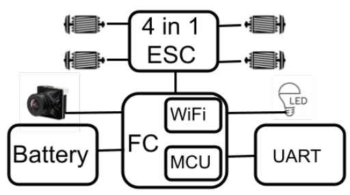
Figure 3 shows the architecture of today’s drone electronics [66]. One of the most important components, the Flight Controller (FC), stabilizes the FLS to perform precise flight maneuvers. Today’s FCs are circuit boards that adjust the speed of the motors to move the drone in a desired direction. They interface with an Electronic Speed Controller, ESC, that connects to the motors, controlling the speed at which the motors must rotate for the applied throttle. A 4-in-1 ESC allows an FC to control all four motors of a quadrotor.


An FC is equipped with sensors that detect the drone’s movements. Basic FC sensors include gyroscopes (gyro) and accelerometers (acc). While the gyro is used to measure angular velocity, the acc measures linear acceleration. Other sensors may include barometric pressure sensors and compasses (magnetometer). Today’s FC may serve as a hub for other drone peripherals like LED light sources, cameras, and video transmitters (VTX), see Figure 3. A current trend is smaller FCs with more features.


Different FC boards may require different firmware. Configuring the FC’s firmware is the process of adjusting settings of its


Figure 3: Today’s Architecture.


Proportional–Integral–Derivative (PID) controller, RC rates which determine how rapidly the drone rotates about an axis, and others to achieve desired flight characteristics. It strives to harness the full potential of the FC for a target application. A firmware setting may use only one sensor such as the gyro[2] or require multiple sensors[3], such as both gyro and acc.


An FC may include a wireless networking card, and uses a microcontroller unit, MCU, to store firmware data and perform complex computations. At the time of this writing, MCU speeds range from 72 MHz to 480 MHz with memory sizes ranging from 128 KB to 2 MB. The MCUs are evolving rapidly to provide faster speeds and higher memory capacities, retiring older models.


An FC has a Blackbox feature that logs attitude of the drone, gyro sensor measurements, RC commands, motor outputs, etc., which is useful for tuning and troubleshooting an FLS. It requires the FC to have either a flash memory chip (e.g., NOR flash) or a SSD card recorder. The rate of logging is an adjustable parameter. Visualization tools for the Blackbox logs enable a user to select the traces and generate graphs of interest. Example timeline graphs include FC throttle levels, attitude, motor outputs, and PID controller outputs.


Today’s FCs use a hardware serial interface named Universal Asynchronous Receiver/Transmitter (UART) that allows external devices to be connected to the FC. Examples include serial radio receivers, telemetry, race transponders, and VTX control. It is possible to create additional UART ports in the firmware, using the MCU to emulate multiple UARTs. This feature is called SoftSerial. Future FLS Architectures: We envision the future architecture of an FLS will include a System-on-Chip, SoC, and disaggregated designs. The SoC will resemble that of Figure 3 with additional functionality implemented in FC. The disaggregated design is shown in Figure 4. It envisions a plug-n-play system bus that empowers an experimenter to use with alternative devices. The tradeoff between the two include weight, size, and modularity with the ability to switch components. The SoC will almost certainly be lighter and more compact. However, it will be difficult (if not impossible) to change one or more of its components. For example, it may be challenging to replace its WiFi hardware component with the power efficient ZigBee (802.15.4, 2.4 GHz). This may be ideal for a product offering such as a next generation gaming display. However, for research and evaluation purposes, a disaggregated design maybe preferable as it empowers an experimenter to evaluate alternative hardware components and their tradeoff when designing and implementing different algorithms.In essence, one may use the disaggregated design to identify components of a SoC. Below, we describe the disaggregated architecture.


Figure 4: Future FLS Architecture.


There are several differences between the architecture of Figure 3 and the disaggregated architecture of Figure 4. First, the disaggregated architecture requires external devices to interface with the system bus directly, making a UART redundant. Second, it replaces MCU with a Central Processing Unit, CPU. The CPU will host a general purpose operating system. It will enable an experimenter to implement and evaluate diverse algorithms such as collision detection and avoidance [5–7, 12, 13, 16, 17, 23, 24, 31– 33, 35, 44, 45, 47, 53, 54, 67, 70–74, 77], a continuous battery charging technique such as STAG [26], localization [15, 30, 40, 79], 3D audio [25], among others [25]. A Localization device, LOC, will enable the experimenter to plug-in alternative localization sensors such as Bluetooth [48, 75], Wi-Fi [55, 59], RFID [9, 50, 76, 81], UWB [36, 39, 63], Lidar [18, 65], RGB cameras [8, 51, 65, 80] and infrared [35, 54, 57]. They will be used by the software hosted on the local CPU to compute the position of an FLS relative to other FLSs and the display volume.


A challenge of Figure 4 is how to realize a layout that is light, compact, economical, and adjustable by an experimenter with minimal effort. While the architecture of Figure 3 is not adjustable, it is lightweight and compact. For example, SpeedyBee[4] F7 [66] stacks an FC with a 4 in 1 ESC that weighs 19.2 grams with dimensions of 45.6mm (Length) x 40mm (Depth) x 8.8mm (Height) at $119. Ideally, a disaggregated design should closely approximate these specifications, and its future SoC implementations should be orders of magnitude smaller, lighter, and cheaper.


Downwash is the rapid displacement of air by an FLS’s rotors. It may impact the position of other FLSs, resulting in unstable visuals and inconsistent haptic feedbacks. An FLS may use an existing method such as a neighbor-aware states to train its policy to counter downwash [58, 62]. Moreover, FLSs may allocate extra thrust to counteract disturbances. This will require an FLS to provision its thrust to implement other tasks such as haptic feedback.


An FLS has a fixed flight time on a fully charged battery. An alternative is to use a continuous power source such as a laser power beam [2] or a tethered FLS [46] with an umbilical link to a power source. It may also be possible to have a laser beam charge an FLS mid-flight [49]. A charging software solution such as STAG [26] also benefits from a hardware solution that enables an FLS to switch its depleted battery with a fully charged one [69].


Figure 5: Rendering scheme for a single FLS. Force is applied to the user proportional to the distance that the FLS is perturbed away from a setpoint location.


This paper is available on arxiv under CC 4.0 license.


[2] This is the Acro Mode setting of Betaflight firmware.


[3] Examples include Betaflight’s Angle Mode, Horizon Mode, and Rescue mode.


[4] F7 identifies a 216 MHz MCU with either 0.5 or 1 MB of memory.